


WIND (Wind Turbine Blades with Deicing Thinfilm Materials)
OVERVIEW
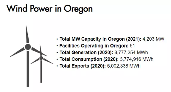
Wind is the second-largest zero carbon electricity source in Oregon state. Oregon’s climate is windy – thus provides great potential for wind renewable energy for the state – but also icy in some regions especially in winter. Often, locations that have the most potential to generate substantial wind power are also remote and potentially very cold. This leads to an increased risk of turbines operating with ice which, in turn, leads to reduced performance or even a complete freezing of the system. Ice often increases vibrations in the system, reduces power output, increases maintenance cost by accelerating wear-out and even stopping power generation all together. These are concerns for Wind power generation in remote locations in Oregon. The WIND project (Wind Turbine Blades with Deicing Thinfilm Materials) is aimed to solve this problem with novel thin film materials to help protect and de-ice wind turbine blades.

Oregon’s Roadmap for clean energy has the goal of half the total energy portfolio coming from renewable energy by 2040 [2]. Key renewable energy sources include [2]:
Wind Energy
Solar Photovoltaic and solar thermal energy
Wave, tidal and ocean thermal energy
Geothermal energy
Certain biomass products, including woody biomass and animal manure
Landfill gas and other biogases
Small hydropower
Thermal energy
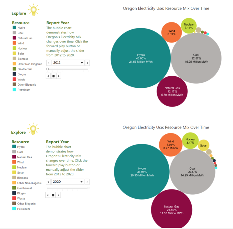
Wind is expected to play a decisive role in Oregon’s ability to meet this target. The State of Oregon has demonstrated that Wind is scalable, increasing its electricity use mix from 5.39% Wind in 2012 to 7.01% Wind in 2020.
FACTORS REDUCING WIND SCALABILITY
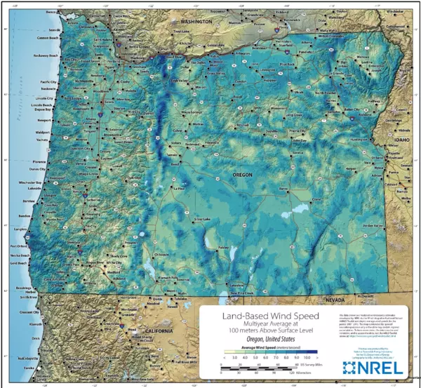
As illustrated in the figure, some of the most inhospitable and coldest parts of Oregon happen to offer the best potential for Wind power generation.
Ice on the turbine creates significant challenges to Wind Power Generation which include increased downtime and higher failure rate. In addition to increased costs, increased downtime is also a consideration as maintenance is often difficult in these locations. These are concerns for Wind power generation in remote locations in Oregon and is of great concern in many parts of Canada.

CURRENT STATE
Many efforts have been made to reduce or eliminate the impact of ice on the performance of Wind Turbines. These include both active (requiring energy) and passive (does not require energy). Passive techniques often center around reducing the ice adhesion strength to the turbine blades thereby making removal of ice easier. Active techniques include hot air injection where the turbine and air immediately next to it are heated above the melting temperature by flowing hot air [3]. Still other methods include mechanically scrapping the ice or the use of ultrasonic de-icing.
While hot air injection has proven successful it does have some limitations. Traditionally, the thermal source is located at the hub and thus the hot air is required to flow long distances to reach the edge of the blades, a process that is energy inefficient and becomes even more problematic the longer the blades become [3]. To help mitigate this, resistive heaters have been suggested as a solution. In this method, heaters are bonded to the blade’s outer surface. While this has some performance advantages, the system can de-bond in the field or experience other reliability issues [3]. A new generation of reliable, high performance resistive heaters are required, preferably ones that have good wear properties, excellent thermal performance and can easily and cost effectively be applied to Wind Turbines without disturbing the flow of air over the blades.
PROPOSED SOLUTION
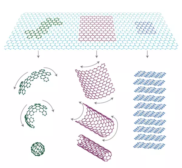
Graphene and related materials, such as Carbon nanotubes hold great promise as next generation engineering materials that offer remarkable thermal, mechanical, optical, electronic performance potential. For this reason, the 2010 Nobel Prize in Physics was awarded to Andre Geim and Konstantin Novoselov of the University of Manchester “for groundbreaking experiments regarding the two-dimensional material graphene” [4]. The figure below shows the different forms of Carbon and, conceptually, how Carbon can be manipulated either by folding in on itself to create Fullerenes or rolled on itself to create Carbon Nanotubes (CNT).
In terms of thermal properties, the performance ability of CNT is immense. According to Yu et al: “the thermal conductivity of isolated CNT was predicted by molecular dynamics simulations to be 6,600 W/mK that is as high as diamond” [6]. For comparison, Copper has a thermal conductivity that is about 400 W/mK. While CNTs seem to offer a clear performance advantage over traditional metals, the use of CNT to create resistive heating elements for Wind Turbines is more complex. One potential solution for how to harness CNT for Wind Turbine de-icing is suggested by Zhou et al [7]. They showed that CNT could be dispersed inside of Waterborne PolyUrethane (WPU). In WPU they tend to form a dense layer that has exceptional thermal and mechanical properties, similar to the underlying CNT’s that are a key building block of this system [8, 14]. This system is a complex composite with one component being polymer and the other component being a nanoparticle or nanotube. In addition, the interaction between nanomaterials and the polymer is both complex and important in determining the mechanical properties of the system [8].
Polymers and nanomaterials can be combined to form a variety of engineered materials with properties tailored specifically to the application of interest. These include nanoparticles, nanowires (such as CNTs), and nanosheets. The figure below illustrates the different classifications of nanomaterials and some of the common materials used in each.
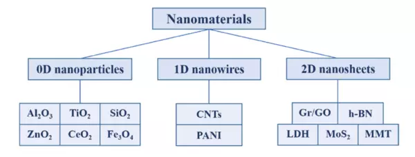
Nanomaterials, including nanoparticles and nanowires are intriguing because a host of properties such as thermal, mechanical, electronic and optical can be modified by placing them inside of a polymer matrix. When first making an approximation, one can think of the composite as being a weighted average of the matrix and the dopant and thus the property of interest (Thermal Conductivity, Young’s Modulus etc.) can also be thought of as a weighted average of the matrix and the dopant properties. While a good starting point conceptually, in practice there are complex interactions between the matrix (polymer) and the dopant (CNT) that need to be accounted for to build a truly robust model. Only a robust model has the ability to predict the properties of interest. Key properties for any model to consider include nanomaterial size, morphology and chemical composition [8]. Common properties nanomaterials are used to modify and improve within the matrix include strength, toughness, shrinkage, corrosion resistance, wear resistance, flame resistance and anti-static properties.
Nanoparticles, or 0D nanomaterials, can often fill the pores formed by local shrinkage during the curing process of the waterborne resin [8]. Typically spherical in shape, these nanomaterials tend to form strong crosslinks with the polymer matrix. TiO2 and Al2O3 are common nanoparticles used in these systems. Nanowires, or 1D nanomaterials, are often arranged crosswise in the polymer matrix. This means they can impart excellent corrosion resistance to the composite system. Important variables to consider include nanowire composition and length.
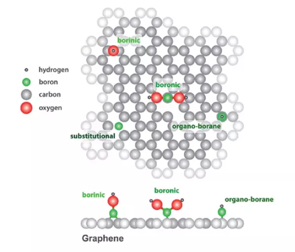
In addition, the incorporation of CNT into the polymer matrix allows control over the electronic properties by adding dopants to the CNT. This will change the number of free carriers available for conduction. Since CNT are tubular, or rolled sheets, of Carbon atoms, the bonding consists of sp2-hybridized Carbon atoms arranged in a honeycomb lattice [9]. There are several ways of doping CNT, one is analogous to the method used in thin films and one specific to CNT. Since CNT are a monolayer of Carbon, molecules can be absorbed on the surface of the CNT that can modify the electronic properties of the CNT. Agnoli and Favaro show that molecules with Boron (Figure 6) can bind on the surface of Carbon [10]. This process can be used to modify the system creating p-type conductivity in graphene.
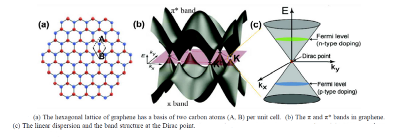
Another method that is similar to the traditional doping mechanism of semiconductor thin films is adding electron surplus or electron deficient atoms directly to the lattice to induce either n-type or p-type conductivity. CNT and graphene can be doped with Li, B, N, S, P, K and Ni [9]. Graphene is intrinsically a zero-gap semiconductor as the Valance Band (VB) and Conduction Band (CB) touch. However, depending on the type and concentration of doping used the Fermi Level can be moved either into the CB (n-type) or into the VB (p-type).
The band structure and therefore the band gap of CNT is more complex than graphene because additional considerations such as the diameter of the tube must be accounted for. As demonstrated by Kumar, CNT can be either zero-gap or a semiconductor (non-zero band gap) depending how they are fabricated [12].
Boron is a well-studied p-type dopant both in Silicon and Graphene and Nitrogen is its n-type counter point. These dopants can be used to change the positions of the Fermi Level, as shown in the band diagram and Density of State calculations presented below.
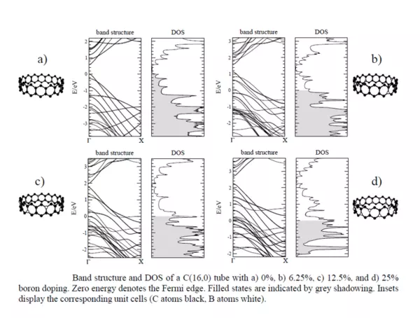
It shows that positions of the Fermi Level can moved based on the type and concentration of the dopant. In this case, a p-type semiconductor can be created.
APPLICAITON TO WIND ENERGY
By combining insights from Chemistry concerning CNT incorporation into polymers and insights from Materials Science concerning doping of materials to change their electronic properties, the creation of a better de-icing system for Wind Power is possible. CNT will be doped using both n- and p-type dopants to control the electronic properties. These will be imbedded in a flexible polymer matrix, one that has the ability to stretch and conform to the shape of a Wind Turbine, and additional shapes as required for other applications. Then the electrical performance thin film will be optimized by considering the dopant type, dopant concentration and the geometry of CNT. Finally, their effectiveness and de-icing technology for Wind Power will be explored.
Important Vocabulary
Fullerenes – A form of carbon which contains a molecule consisting of a hollow cage of atoms in a large spheroidal shape.
Conductivity – The degree of which a certain material carries a current of electrons (electricity)
Nano – 1/1,000,000 of a meter
Dopant – A substance used to produce a desired electrical characteristic in a semiconductive material
Young’s Modulus – a measure of elasticity using a ratio of stress to strain
Matrix – material that provides the composite its shape; reinforces the fibers
Robust – Vigorous, strong and healthy
Morphology – The study of how things form and the resulting formations
Free Carriers – A radioactive isotope that is free from stable isotopes of the element
Analogous – Comparability in certain respects to clarify
Fermi Level – The highest energy level that an electron can occupy at the absolute zero temperature
[1] Jumani, S. et al. Environmental Challenges 12 (2023) 100731.
[2] Oregon Department of Energy. Energy in Oregon. Wind.
[3] Renewable and Sustainable Energy Reviews 65 (2016) 662–675.
[4] Nobel Prize Official Webpage.
[5] Science. 19, June 2009. Vol 324.
[6] Yu et al. Nano Research volume 14, pages 2471–2490 (2021).
[7] Zho, et al. Progress in Organic Coatings 142 (2020) 105600.